ACF2D - Axial Compressor Design Tool
AixCompFlow 2D (ACF2D) is a design software and tool based on a streamline curvature method for analysis and design of multi-stage axial compressors. It combines the special expert knowledge and adapted compressor profile correlations to a highly efficient and reliable design tool with special focus on axial compressors for heavy duty and industrial gas turbines for electric power generation.
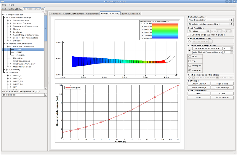
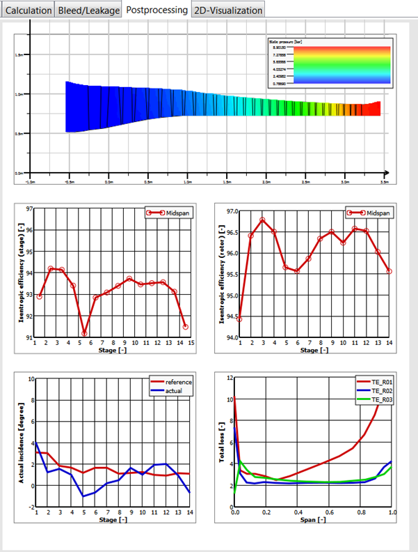
The software is available for Windows and Linux operating systems. The graphical user-interface provides access to all input data as well as the possibility to analyse the results in chart plots and 2D plots.
ACF2D can be run in batch mode and in script mode for easy integration into client's compressor design and optimization tool chain and for calculation of compressor maps within short time.
Newest Models and Features in ACF2D
- enhanced possibilities for adjusting the implemented correlations to client specific needs and experience
- correlation adjustment can be done per airfoil family and per blade row
- enhanced model for rotor and stator tip clearance losses
- consideration of adjustable rotors
- export of calculation results per station (integral results) and on streamlines (2D results) into CSV format
- consideration of radial distribution in case of mass flow extraction (bleeding)
- influence of surface roughness (deterioration) on compressor performance
ACF2D Analysis Mode
As in the previous versions of ACF2D, also the newest release can be run in the analysis mode. Here, the geometry of the compressor is prescribed and the flow and performance of the compressor are calculated by application of the implemented loss and deviation correlations for the following profile families:
- NACA65 (according to NASA SP-36)
- DCA (double circular arc) (according to NASA SP-36)
- CDA (controlled diffusion airfoil) (self-developed correlation based on DCA correlation)
- NACA63 (self-adopted NACA65 correlation for NACA63 airfoils with high flow turning as used for IGVs)
- MCA (multi-circular arc) (according to Koch&Smith)
ACF2D Design Mode
In the analysis mode of ACF2D, the airfoil geometry is prescribed by means of geometry parameters, so that the outflow condition for each blade row can be determined based on the implemented correlations for total pressure loss and deviation. In the design mode, the outflow condition itself is prescribed by user input. Thus, the desirable flow condition of the blades and vanes can be analysed in the environment of the entire compressor. The analysis mode and the design mode can be arbitrarily combined in one calculation, i.e. some rows are calculated in design mode and the others in analysis mode.
The outlet flow conditions can be prescribed by
- profile loss & relative outlet flow angle.
Outlet conditions can have different geometric dependencies:
- radial coordinate,
- span (relative flow channel height) or
- streamline number
and also aerodynamic dependencies with respect to relative inlet Mach number and relative inlet tangential flow angle. The necessary 2D data and corresponding XML files, which are used by ACF2D, can easily be created, evaluated and manipulated by means of the B&B-AGEMA tool PDEM (Performance Data Evaluation and Manipulation tool). The 2D data are interpolated by means of 2D Akima splines.
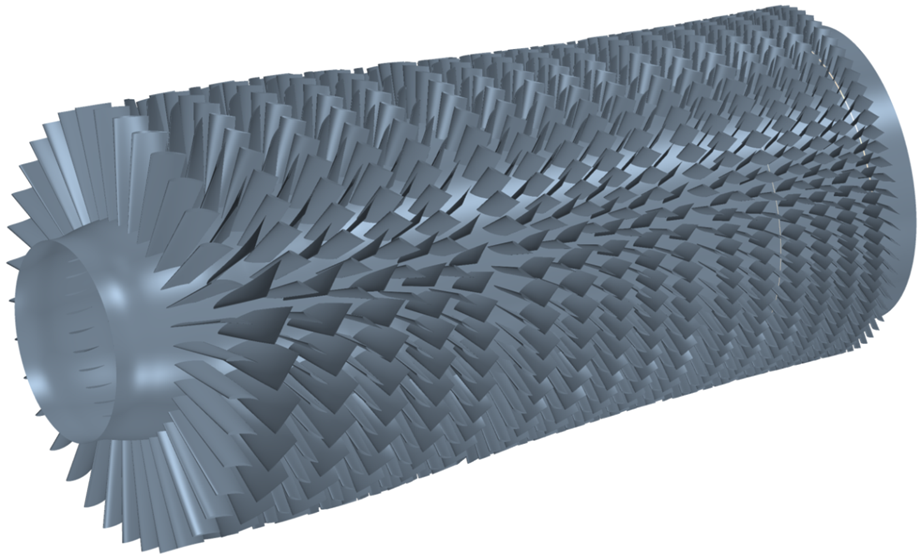
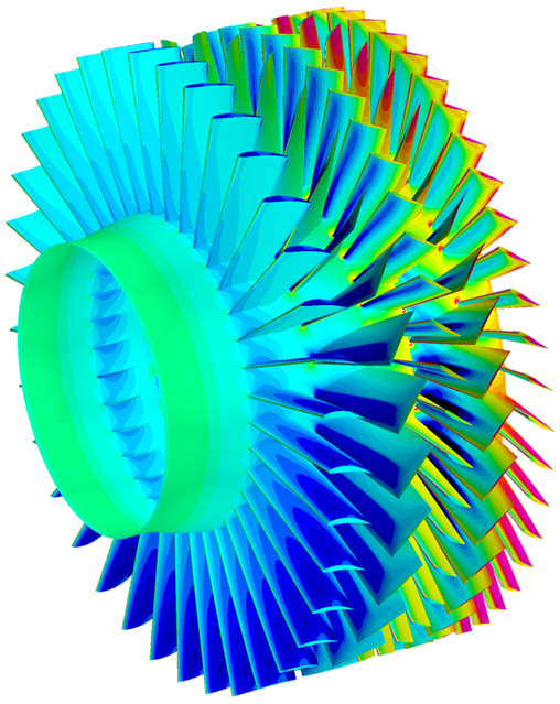
Example calculation of a 16-stage gas turbine compressor with ACF2D
Automatic export of the 3D compressor geometry from ACF2D and calculation with CFD